
To V or Not To V ..
Today’s topic is surrounding the Spin Semiconductor FV-1 chip, some of the debugging processes of getting it up and running via a third-party development board, and why I’ve decided to finally give it a try. I won’t be really covering the history or applications of the chip, although I share some personal opinions of its sound, as well as a few of its specifications while explaining the set-up process of the third-party dev board.
Table of Contents:
· Avoidant Insecure
· Transparency Via Education and Customer Research
· New Builders and the Path to Discovery
· FV-1: The Hacker’s Intro to Digital
· Pedal PCB Process vs Traditional Spin Dev Boards
Avoidant Insecure
I’ve been avoiding designing effects based around the FV1 for so long for two main reasons: The first being I’ve owned quite a bit of pedals at this point that used this chip and I could never get them to integrate to my existing pedalboard set up, and the second being it seemed like there was a time where everyone was using this chip (and still is) and it was difficult to come up with something that didn’t sound like it was using the chip or had already been done, as well as the Covid supply chain issue that seemed to have been a scare for companies buying FV1s on a large scale.
The main thing I didn’t like about the chip was how the mix sounded. Each commercially made FV1-based pedal usually comes with a mix control of some sort, and to me the dry is too dry, while the wet is too wet, never really finding a good middle ground. Even with the Mix at Noon on most pedals, the clean is still a bit too sterile, especially in the Reverb-based algorithms. I’ve recently purchased a pedal however from a well-known company to revisit its sound and to honestly take it apart and trace some of the connections. Not to copy the circuit (because the main magic of the circuit is stored in an EEPROM) but to see which connections they were making to the switch that selects the algorithms in comparison to the schematic I had from the third-party dev board. (PedalPCB FV1 Dev Board) For example 8 patches can be stored and selected in the EEPROM while my board can only select 3, so looking at different schematics of how to connect more, while tracing a pedal that’s using one commercially was a big help in understanding its application.
So why am I finally coming around? The main answer to this question is simply that I want to challenge myself and experience something new. Figuring out the set up alone isn’t a cake walk, especially with the workarounds of using a “knock off” of the real thing, let alone learning how to program in the software. I am not putting any pressure on myself to release an effect that is FV1 based, and I want to see if I can come up with something fun and unique for myself. Maybe once I really get the hang of it and how the programs work, I can come up with something truly different that will be useful to others.

Pedal PCB FV1 Dev Board as it looks upon arrival. The only things soldered are the FV1 itself (left) and the USB Bus Controller (right)
Transparency Via Education and Customer Research
Why am I even bringing this up? Surely it seems like discussing the inner workings of a digital guitar effects platform isn’t relevant to the average consumer. I would say nay. In the age of content, more and more companies and individual builders are pulling back the veil on their approach to running a pedal business and processes that go along with that. Most notably, Josh Scott of JHS is the pioneer of intertwining consumers with the history of pedals and demystifying the circuity behind them. Countless other companies are doing the same (even me writing this now), and as interests in pedals grow not only as a tangible thing to create with, so are the expectations surrounding what’s inside and what makes a pedal different from others.
This leads me to the topic of customer research. As stated above, many companies are providing consumers with the tools to understand what makes pedals different on the inside. There may have been a time in pedal history where customers who were not engineers marveled at the Phase or first Fuzz units, but now the internet is a thing and schematics are rampant (Interestingly enough, Keith Barr who designed the Phase 90 is also responsible for designing the FV1). Before purchasing a pedal, a lot of consumers are watching YouTube demos, listening to Podcasts, and doing their own research on the internet. Consumers talk amongst themselves in forums and platforms like Reddit discussing much of what builders discuss without being builders themselves. They are understanding the jargon and the difference between the “magic” Klon diodes, the sacred Rat LM308 chip, the PT2399, and ..the FV1. As more information about pedals become widely accessible and the mystery behind them fades, a builder’s approach becomes more vulnerable and less protected as consumers gain knowledge of what is going on inside by simply removing 4 screws.
It's also worth noting that in parallel to companies sharing practices with customers, materials like “Pedal Crush” by Kim Bjorn and Scott Harper are dissecting pedals down to the core. They have essentially created the encyclopedia of pedals through rigorous research and interviews, while breaking down each individual category a pedal may fall into. “The Pedal Movie” by Reverb.com is another example of trying to educate and inform consumers about pedals.

Dev Board after soldering most of the small components and IC sockets. The only thing left is the pots, USB port, Voltage Regulator, and the Crystal Oscillator
New Builders and the Path to Discovery
Before we can continue discussing why the FV1 has become so popular and widely used, we must discuss the general path of a builder. This is obviously different for many people, but as the market is becoming saturated and straying far from the boutique days of DIYStompbox forums, Keeley, Analog Mike, ZVEX, Way Huge, and Wampler, (to name a small few) more builders are entering the market every day.
Most new builders coming from a DIY background like myself start with building dirt pedals, and some even release these as their flagship pedal to announce their emergence onto the pedal scene (and survive solely on it). Simply put, dirt pedals are some of the easiest and simplest circuits to begin with and are extremely modifiable. It goes without say that they can also be extremely large and complex. This is a great platform to learn a lot about pedal building. My personal approach to releasing pedals to the public was very similar. I released a small batch of 10 pedals called the Designated Driver as my first experiment of producing pedals, buying parts, ordering enclosures, and building with consistency. There is one demo of its existence done by Pedal of the Day. There is a reason why I’ve never made any more than that..
As the path continues for the DIYer who has graduated from dirt boxes, next in line is the PT2399. As mentioned above, consumers are well-aware of what this chip is and can likely identify which pedals use it just by hearing it. The reason why a lot of DIYers use this chip is because of its ease of application and modification, as well as the “analog” qualities that come with it (this is a digital chip with A/D converters and RAM storage to create delay). A builder can really stand out and create something unique with this chip that enters modulation, delay, and reverb territory which can all be achieved with different applications. We arrive at the exact moment in Retroactive history, where after nearly 10 years of experience I have released three pedals that are based around this chip. Albeit my third pedal the Validity Sensor uses the Belton Reverb brick, Accutronics and Brian Neunaber designed this by using 3x PT2399 chips in series.

A plush sticker of an American classic adorns my coffee mug of tools. Won at the pier in Old Orchard Beach, ME
FV-1: The Hacker’s Intro to Digital
Finally, we enter the summation of what this article is really about and the culmination of where I stand as a builder. For most of us who aren’t equipped with the resources or abilities of Strymon, Line 6, Hologram Electronics, EHX, Chase Bliss, or any of your favorite digital guitar brands that are inventing some of the most purchased effects on the market today, we result to the FV1. It’s worth noting that EHX and Chase Bliss both have used this chip in their pedals, as well as more professional means of DSP.
Without getting too technical of what the FV1 is or does, here is a great article to read. Reverb.com even wrote a piece on its popularity.
The reason why a lot of builders like myself gravitate towards the FV1 is because of its approachability to understanding digital circuits without compromising the foundation of what took us so long to understand about pedals in the first place. Not to mention it’s open source! Most all of this would not be possible without the efforts of Digital Larry at Holy City Audio for designing SpinCAD. SpinCAD is a GUI that allows the user to connect blocks, or patches of effects together which can be spit out into binary code that can be compiled to the EEPROM. This eliminates the user of having to understand the lengthy coding of SpinASM altogether. You can simply try and try again until you design something you like with a visual representation to boot.
PedalPCB Process vs Traditional Spin Dev Boards
I will attempt to not get carried away here and try to keep this information concise, but also supply information to anyone trying to get set up with the Pedal PCB dev board and may have run into issues. To convey the difference between the Pedal PCB FV1 Development board I purchased, and the Spin Semiconductor made dev board, I will try to lay out the very basics of what is needed to get started down this path as well as a small amount of backstory.
Spin Semiconductor (maker of the FV1) made development boards for consumers to purchase and experiment with designing audio. To my knowledge, when it was first released, the only program compatible with compiling and writing code was called SpinASM. Understanding the coding can be a little daunting as I myself haven’t given it much effort. Since this platform was always open source, we then see the emergence of SpinCAD. This was a Java designed GUI by Digital Larry to integrate with SpinASM in a more digestible format. Users can use SpinCAD to design the circuit visually, and then export the .spcad file to SpinASM to compile it to be uploaded to the EEPROM chip. To my understanding these Spin-made dev boards are no longer available brand new, and they’re hard to find on the used market and they can be quite expensive.
Since it’s open source, we now see the production of other development boards, which is how I purchased mine from Pedal PCB. Now, here is where I’ll try to really reign it in, because there is a huge difference between the two as far as getting it up and running successfully. I’ll lay out a few of them here without going too hard, and if anyone is experiencing issues, please reach out to me and I will gladly explain the process in more detail.

Download Link to SpinCAD Designer from Holy Island Audio’s GitHub page located in the Assets folder
The first step is to download the “SpinCAD-designer-build-1032.jar” file from Holy Island Audio’s Github page which I linked to above. Once you download the file, you’ll need to download Java to run the program. Technically you don’t need to download SpinASM at all to successfully import your circuits to the EEPROM. At first I downloaded it because the USB Driver is in the .zip file that comes with SpinASM, however Pedal PCB must use a different USB Bus Controller to write to the EEPROM, because I couldn’t connect using the original driver.
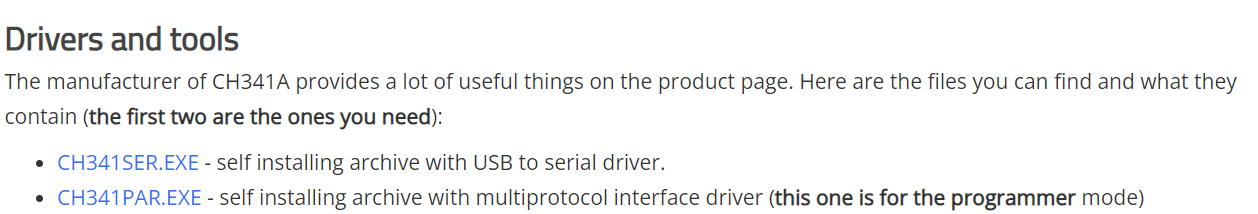
Driver link for the CH341A USB Bus Controller from www.onetransistor.eu
You will need to download 2x drivers from a different location to work with the IC CH341A USB Bus Controller. Those can be found here. This information wasn’t included in the build documents, I had to find this scouring a forum, so I’m hoping this is useful information to others. I’m not sure if both drivers are actually required, but it’s what someone mentioned in the forum and I got it working that way.
Finally, you will need another program called “AsProgrammer”. This is needed to compile and write code to the EEPROM. This is used as a substitute for not using the complier and USB Bus Controller driver that comes with SpinASM.
Another semi-complicated thing to note is that the benefit of using the real thing and exporting your files from SpinCAD to SpinASM is that SpinASM can read .HEX files, which is one file type you can export straight out of SpinCAD seamlessly for compiling, whereas AsProgrammer can only read .BIN files. You will need to save your SpinCAD project as a .HEX file and use the command prompt on your PC to navigate into the folder where it’s saved to convert it to a .BIN file (the command can be found here and you need to remove the “<>” from the function). You can’t simply rename the file and change the file type unfortunately, I tried.
The Holy Island Github page, among others, has plenty of open-source patches for downloading and testing to make sure everything is working properly. Once you’re up and running, try editing the existing patches to figure out how everything works in SpinCAD. That’s pretty much where I’m at myself. Hopefully soon I’ll be able to release something that’s worth it, but in the meantime, I’m just having fun experimenting and learning something new and I encourage you to do the same. If anything here doesn’t make sense or if you’re having trouble getting your Pedal PCB dev board connected, please don’t hesitate to reach out.

Fully wired and working unit

Finished product and skeptical bystander